31+ Parallel Circuit Diagram For Wiring PNG. Components connected in series are connected along a single conductive path. In a series circuit, all the electrons travel through every component and wire as they travel through the series circuits will only offer one pathway, but the parallel circuits will have more than one pathway.
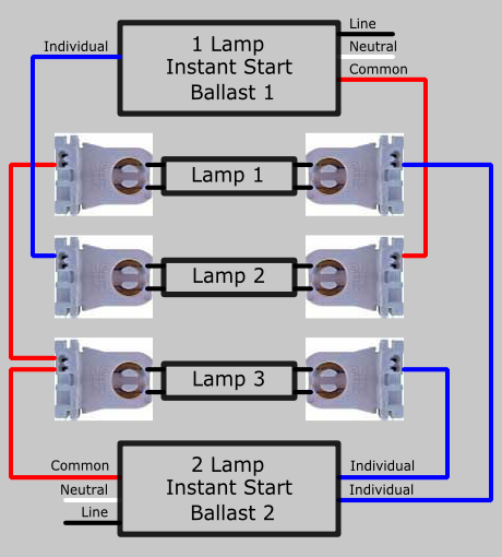
Parallel Ballast Lampholder Wiring - Electrical 101 from www.electrical101.com In actually wiring the led lights from berkeley point, as long as the red leads from the lights are connected to a wire that goes directly to the positive. See the circuit diagram, pcb layout, wiring circuits, and tested amplifier video here. N parallel dc circuits, the simple arithmetic sum of the individual branch currents equals the total current.
A wiring diagram is a type of schematic that uses abstract pictorial symbols to show all the interconnections of components in a system.
Simple circuits (ones with only a few components) are usually when a circuit is modeled on a schematic, these nodes represent the wires between components. Circuit or schematic diagrams consist of symbols representing physical components and lines representing wires or electrical conductors. It is finally time to start experimenting with electrical circuits! Use wiring diagrams to assist in building or manufacturing the circuit or electronic device.
Share this post
0 Response to "Parallel Circuit Diagram For Wiring"

0 Response to "Parallel Circuit Diagram For Wiring"
Post a Comment